
IES ConcreteSection User's Guide
Stress Results
When building the Interaction Surface, ConcreteSection solves the problem of: given a axis offset, neutral axis angle, and ultimate strain, determine the resulting axial force and bending moments (P, Mx, My). The Stress Results feature in ConcreteSection solves the inverse problem: given applied axial force and bending moments (P, Mx, My), determine the corresponding axis offset, neutral axis angle, and the resulting stress and strain distribution. See the Analysis section for the fundamental mechanics underlying the solution to both problems.
Finding the neutral axis offset, neutral axis angle, and extreme fiber strain from an applied axial force and bending moments (P, Mx, My) requires solving a system of three equations and three unknowns. All of the variables are coupled making the system of equations non-linear. Mathematically this is an optimization problem where ConcreteSection finds the combination of neutral axis offset, neutral axis angle, and strain that minimizes the difference between the integrated stress over the cross section and the applied loads. ConcreteSection uses the Levenberg–Marquardt algorithm to perform this minimization.
Note: The Stress Results view is inactive if no loads are applied to the reinforced concrete section.
The Stress Results view graphically displays the behavior of the cross-section for the result case selected in the tab. It includes the cracked neutral axis offset and angle, as well as the stress or strain in the concrete. For reinforcement, the force, stress, or strain can be viewed individually for each bar. Use the to control which results are displayed for both concrete and reinforcement. Color contour legends help visualize and adjust the range of values shown.
The tab displays several sets of results in the Case Summary for the selected result case, including: the applied axial load and bending moments; cracked section properties; concrete stress and strain ranges; reinforcement force, stress, and strain ranges; and Convergence Error—the difference between the applied loads and calculated results.
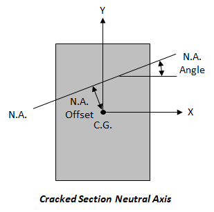
Note: The cracked neutral axis offset and angle of rotation reported under the cracked section properties are measured with respect to the centroid of the gross concrete boundary and the X-axis, respectively, as shown in the figure below.
Select the concrete or reinforcement bar(s) to view the numerical results in the tab for the selected Result Case.