
IES ConcreteSection User's Guide
Analysis
ConcreteSection performs two distinct analysis tasks:
This section outlines the mechanics of materials approach and the assumptions that are common to both types of analysis in ConcreteSection.
Reinforced concrete combines two distinct materials—concrete and steel—with fundamentally different mechanical behaviors. Concrete is strong in compression but weak in tension, while steel provides strength in both tension and compression. To accurately determine the response of a reinforced section under load, three foundational principles must be considered: strain compatibility, material constitutive models, and equilibrium. These principles work together to determine the internal forces and overall response of a section subjected to axial and bending loads. The behavior of the reinforced concrete section is determined by dividing the section into a triangular mesh and applying these three principles of mechanics as detailed below.
The assumption that plane sections remain plane means that cross sections do not warp during bending, resulting in a linear strain distribution across the section depth. Additionally, strain compatibility assumes a full bond between steel and concrete, so both materials share the same strain at their interface. Together, these assumptions define how the section deforms and enables the calculation of strain at each node in the section mesh.
Constitutive models describe the stress-strain behavior of the materials in a reinforced concrete section. Steel typically follows an elastic-perfectly plastic response with similar behavior in both tension and compression, while concrete exhibits nonlinear behavior in compression and has negligible tensile strength. These models are used to convert the calculated strain distribution into internal stresses within each element in the section mesh.
An elastic/perfectly plastic stress-strain relationship is used for tension and compression of the steel reinforcement in ConcreteSection.

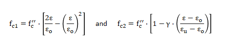
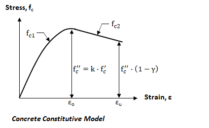
In ConcreteSection, concrete is assumed to have no tensile strength. In compression, the stress–strain behavior is defined using four key parameters: the strain at maximum stress (eo), the ultimate strain (eu), the maximum stress factor (k), and the confinement factor (g). The maximum compressive stress (f″c) is calculated as k × f′c, where f′c is the specified concrete compressive strength. This maximum stress occurs at eo. At the ultimate strain (eu), the stress is reduced to f″c × (1 - g). A higher confinement factor (g) results in a lower ultimate stress, effectively reducing the influence of confinement. All four parameters—eo, eu, k, and g—can be customized in ConcreteSection. The stress–strain relationship is illustrated below, with the corresponding equations for the two segments. Note: The Failure Strain—the strain in the section's extreme fiber when the section reaches full capacity—can be set to either εo or εu in the program. This setting affects the calculated section capacity, as discussed in the Interaction Diagrams section.
The principle of equilibrium requires that the applied forces and moments are balanced by the internal stresses within the concrete and steel. In ConcreteSection, these internal forces and moments are computed by numerically integrating the stresses over each triangular element in the mesh.