
IES VisualFoundation User's Guide
Grade Beams
Modeling grade beams in VisualFoundation is done by setting the drawing mode to "Draw Grade Beams" from the tab and sketching them onto the footing defined in the model. Grade beams have the ability to distribute applied loads to the concrete boundary and add stiffness to the plate model. The concrete compressive strength (f'c) is set using the concrete material for the project, which can be found in the tab with nothing selected. Grade beams that adjoin one another, regardless of orientation, are modeled such that load transfer (i.e. shear and moment) occurs between the members. In other words, there are no end release options with beam elements.
Grade beams also have the ability to increase or decrease the soil subgrade modulus below themselves. Only the nodes defining the grade beam will be affected, in other words, a single line of springs will be modified in the FEA model. To change the subgrade modulus, select one or more grade beams from the Model and Load view and set the Change Subgrade parameter to "Yes" from the tab.
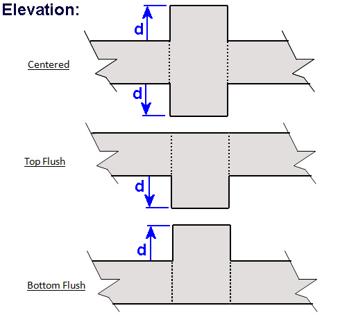
Grade beams are rectangular in shape and have a specified Width and Projected Depth. All beams have a Vertical Offset Type and Length (defined by vertex location). They also have an option to include or exclude the member's Self Weight in the model.
Vertical loads and moments in two directions may be placed on grade beam members. Applied loads are uniformly distributed along the full length of the member and may be entered as linear quantity (per unit length) or as the resultant total. Loads can also be applied in the Global directions or the member's Local directions, allowing the loads to be easily placed parallel or perpendicular to skewed members. You may optionally include horizontal shear forces for sliding checks on the foundation, these forces are assumed to act at the to of the foundation slab.
During the finite element analysis, grade beams are member elements within the same plane as the plate elements with stiffness adjustments based on the Vertical Offset Type setting (parallel axis theorem).
The results from the finite element analysis can be displayed graphically from the Analysis Results view. The tab displays the numerical results that correspond to the colored graphics. With nothing selected, the results displayed in the Project Manager are a summary for the selected result case, whereas if a single grade beam is selected, the Project Manager shows the result range for the selected grade beam. The various Result Cases that were included in the finite element analysis can be selected using the Result Case drop down from the tab. Furthermore, moment, shear, and displacement diagrams for each result case can be viewed using the tab. Analysis results can also be reported in tabular form using the Text Reports.
ConcreteBending checks and designs concrete beam members according to specifications listed below.
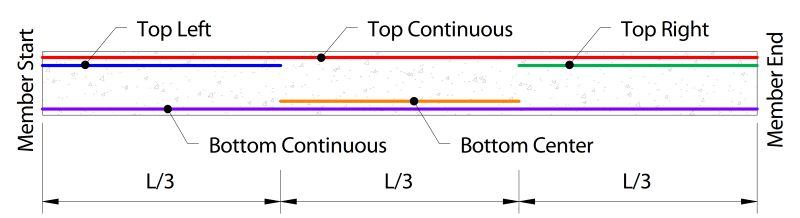
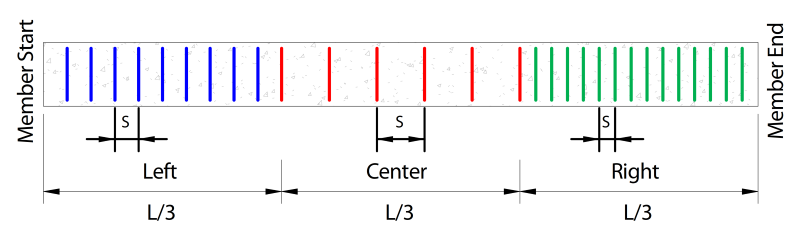
Longitudinal and transverse reinforcing vary along the length of the member, as shown below (respectively).
When designing beams, several parameters must first be defined. These parameters can be set by selecting a beam from the tab and using the tab.
Specification: The Design Specification used to design the grade beam.
Disable Checks?: Causes selected design group to be omitted from design checks.
High Seismic? - (ACI Only, Use Reduced PHI Factors for Members Resisting Earthquake Effects): This tells the design module to apply the lower PHI factors as indicated by ACI 318 Section 21.2.4 for members which are designed to resist earthquake effects and are part of a structure that relies on special moment resisting frames or special structural walls to resist earthquake effects. Note that the program relies solely on this parameter in determining whether or not to use the reduced PHI it does not attempt to calculate whether the shear capacity is greater than the shear corresponding to the development of the nominal flexural strength of the member. Only the PHI factor for the shear is affected by this entry.
Overstrength?: Causes the member to be designed using overstrength load combinations.
Check Level: Determines the level of detail reported from design checks. Options are: To Failure (Fastest), Each Limit State, and All (Slowest, but provides the most information).
Start/End Column Widths: Widths of supporting columns at start and end of grade beam. These widths are used for determining where critical shear and moment sections are at the ends of the grade beam.
Shear "@ d" from start/end: Should shear demands within "d" of the support face be excluded from the checks?
Use Metric Bars?: Should reinforcement be limited to metric bar sizes?
Longitudinal Fy: Specified yield strength of the longitudinal reinforcement in the grade beam.
Size/Count:The size and count of the reinforcement throughout the various beam regions.
Fy: Specified yield strength of the stirrups in the grade beam.
Size: The size of transverse reinforcement.
Are Stirrups Closed? Are closed stirrups used throughout the section?
Spacing: The center-to-center spacing of the stirrups. A different stirrup spacing can be specified for each 1/3 of the beam length. A spacing of 0 means no stirrups are provided.
Top, Bottom, Side Cover: Concrete clear cover for the section. Calculated as the distance from the face of the concrete to the stirrups.
Grade beam results can be viewed graphically from the Design Results tab. By default, the grade beam members display their controlling unity; however, if you would like to display design results of a specific type, such as the Shear Check, this can be done under the Grade Beam Details category of the tab by changing the Design Information drop-down menu.
Design results can also be viewed in text form using the Text Reports tab. Once on the Text Report tab, a list of available deign tables is shown on the tab and can be added to the text report by double-clicking an individual table or dragging and dropping a table into the report.