
IES VisualAnalysis User's Guide
Deflections Checks
Deflections are checked for load combinations that are marked as Deflection or Allowable and Deflection in the Load Case Manager. To perform deflection checks, you must set the Deflection Limit Type (Member Span Ratio, Member Deflection, Total Span Ratio, Total Deflection) in the Design Group. Note: The deflection preference can be used to set this automatically. Once the limit type is set, you can specify the deflection limits (span ratio or deflection value) for the various load case categories (L only, W or S only, D + L, or Other).
VisualAnalysis provides two methods for measuring deflection:
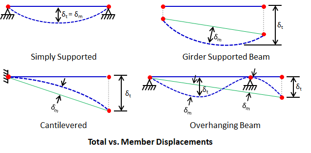
In the figures above, total deflection (δt) is measured as the maximum displacement from the original, undeflected position. Member deflection (δm) is measured as the maximum offset between the deflected member shape and the straight line between its deflected end nodes. Member and total deflection can be the same or different depending on modeling conditions:
Deflection limits may be specified using either:
Span-ratio limits are useful when grouping members with different span lengths while maintaining a consistent deflection criterion. Deflection value limits are useful when a fixed maximum deflection is required, or when span-ratio limits are not appropriate due to modeling conditions such as interior supports or members modeled using multiple member-elements. For span-ratio checks, VisualAnalysis always uses the member-element length. Supports, releases, or connection conditions within an element do not affect the span length used for the check. As a result:
Because of this behavior, span-ratio limits may not be appropriate for members with interior supports or for members modeled using multiple elements. In these cases, deflection value limits or direct review of reported displacements may be more appropriate.
VisualAnalysis can display the calculated deflection ratio directly on the members in the model. Enable Deflection Ratio under the Member Details Design Filter in the Results View to show the member deflection ratio (L/Δ) on each member. Note: The length used in the calculation is the member-element length.
Deflection load combinations are defined in the Load Case Manager on the Load Combinations tab. Deflection checks are performed for load combinations assigned a Deflections or Allowable and Deflections design category. Deflection limits, specified as either a span ratio or an absolute deflection value, are defined by load case category (L only, W or S only, D + L, or Other) through a Design Group’s parameters. Refer to Loading for Design for additional details.
VisualAnalysis does not directly perform code-based drift checks. However, the program provides several reports that display building-level and member-level drift results, which can be used to evaluate drift requirements and make design adjustments as needed. The Complete Member report item reports the maximum drift values for column members.