
IES VARevitLink User's Guide
Part 1: Exporting a Revit Project to VisualAnalysis
Selecting the option with an active Revit project will allow you to generate a .vap file to be used in VisualAnalysis. The Export Dialog is shown in Figure 2, and will become active when the Export command is chosen.
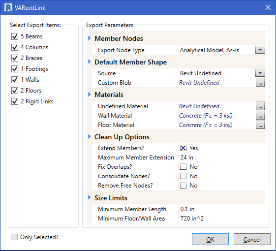
Figure 2: Export Dialog
The left portion of the Export Dialog displays a summary of the items in Revit’s Analytical Model with checks boxes allowing all or a portion of the Analytical Model to be exported. The right portion of the Export Dialog contains a set of Export Parameters that you can adjust to get the desired export model. The Export Parameters are described below.
| Member Nodes |
Export Node Type
Composite Beam? - This option is available when the Export Node Type is set to Generate Centerline Offsets. This value represents the largest offset value to use before separate nodes will be created instead of choosing Revit’s analytical nodes. In some cases, the Revit model might be created with very large offsets and the VA model would not be accurate using these offset values. This is a way to use offsets for small values like setting the beam top to match the slab level and use large offsets to represent “mid-column height” members. |
| Default Member Shape |
Source: This shape will be used if a “similar” VisualAnalysis shape cannot be found. Most Revit Family Symbols can be used to find an equivalent shape in VA. These include rolled steel shapes; concrete circular, rectangular and square shapes; and wood solid sawn, glued-laminated, and machine laminated lumber. When a shape cannot be found in VA, the shape entered here will be used. Use the dropdown to use the VA Shape Database to select the preferred shape. The default value for the Source is Revit Undefined. When left unchanged, VA will generate a blob shape named Revit Undefined, which may be useful to you because once inside of VA, the members can be filtered to quickly locate any shapes that did not match so they can be corrected. |
| Materials |
Undefined Material: This material will be used if a “similar” VisualAnalysis material cannot be found for a member being exported. Most steel, concrete, and wood materials will be matched in VA. The default value for the Source is Revit Undefined. Similar to the Default Member Shape Source parameter, this can be useful in locating any materials that we unmatched during the export process once in VisualAnalysis. Wall Material: This material will be used if a “similar” VisualAnalysis material cannot be found for a wall area being exported. Most concrete and masonry materials will be matched in VA. In the case they are not, this material will be used. Floor Material: This material will be used if a “similar” VisualAnalysis material cannot be found for a floor area being exported. Most concrete materials will be matched in VA. In the case they are not, this material will be used. |
| Clean Up Options |
The VARevitLink offers several options that are meant to help you export the Revit Analytical Model and get a VisualAnalysis Model that closely match one another. The options listed below address many of the common issues that result from differences between Revit and VA. Extend Members?: Check this option to have members which have “free ends” extended to the next crossing member or node. This option is useful to get members which fall short of their connected member to be extended so the connection is made. If you don’t check this option you might get “floating” members which you will have to manually extend in VA so that everything is connected. Maximum Member Extension: This value is available when Extend Members? is checked. If a member’s extension to make a connection would exceed this value the end will not be extended. Fix Overlaps?: If this option is used, the VA model, once created, will be examined for members that overlap each other. The overlapping members will be combined into a single member to eliminate the overlap. Consolidate Nodes?: When checked, any nodes generated in the VA model will be consolidated into one node when within the Close Node Tolerance. This consolidation will occur once all the VA model members and areas have been assembled. Close Node Tolerance: This value is available when Consolidate Nodes? is checked. Any nodes within this distance with other nodes will be consolidated into one node. Remove Free Nodes?: Check this option if you would like to remove any nodes that are not connected to a member or an area once the VA model has been assembled. |
| Size Limits |
Minimum Member Length: If a Revit analytical member has a length less than this value, it will not be imported into the VA model. Minimum Floor/Wall Area: If a Revit floor or wall has an area that is less than this value, it will not be imported into the VA model. |
After all Export Parameters have been set, select OK to save a .vap file of the project. After the .vap file is created, a Summary of the Export operation will display, similar to the one shown in Figure 3. The Summary will note the members and areas that were exported, as well as those that could not be exported. Any “fixes” that were made based on the Export Parameters will also be noted.

Figure 3 - Example Export Summary